

BARREL VALVE REBUILD/INSPECTION PROCEDURES
This tech bulletin outlines the proper way to disassemble, inspect and rebuild a Ron's Fuel Injection barrel valve. The #3014A (pictured below) is gray in color and is the current combination barrel valve being sold with all new Terminator and Flying Toilet systems.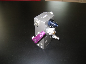
Older, discontinued barrel valves are recognized by their anodizing color. The purple barrel valve last saw production in the year 2003 and is good until the horsepower level reaches approximately 950 horsepower. The oldest barrel valve is black in color and last saw production over twenty years ago. If you have either of these discontinued barrel valves and are having any issues or have over 950 HP we recommend replacing it with a new #3014A unit. We do not offer rebuild kits for the discontinued barrel valves.
Please call us if you have specific questions related to the information supplied in this technical bulletin.
The Barrel Valve O-Ring Kit is $9.00 plus shipping.
Disassembly
1. Remove barrel valve from throttle body.
2. Remove pill plug, pill spring and pill.
3. Remove starter support valve (if used) and inlet fitting.
4. Remove pipe plug from the bottom of the barrel valve.
5. Precisely mark the orientation of the barrel valve spool to its lever with fine point marker or scribe. This is done so that it can be re-assembled to exactly the same orientation.
6. Remove the barrel valve lever and nylon spacer from the barrel valve spool (older barrel valves utilize a drift pin that will need to be driven out before the lever can be removed).
7. Remove the plug from the backside of the barrel valve spool. There will be a spring behind the plug.
8. Carefully push the barrel valve spool out in the direction of where the large plug was installed. Check shaft for burrs before doing this so it doesn’t damage the housing and pushes out easily.
9. Precisely mark the orientation of the shut-off valve spool to its lever with fine point marker or scribe. As above this is done so that it can also be re-assembled to exactly the same orientation.
10. Remove the shutoff lever and nylon spacer from the shutoff spool.
11. Remove the plug from the backside of the shutoff spool. There will also be a spring behind this plug.
12. Carefully push the shutoff spool out in the direction of where the snap ring plug was installed. Check shaft for burrs before doing this so it doesn’t damage the housing and pushes out easily.
13. Verify that the pill 0-ring is in place directly behind where the pill was seated. KillerRONS recommends that you do not remove this O-ring unless you feel that it is damaged and needs replaced.
Inspection and Cleaning
1. Inspect all components for debris and blow out with compressed air
2. Inspect for cut, damaged, flattened or hardened O-rings and replace if necessary. O-ring kits are available affordably from KillerRONS
3. Oil barrel valve spool O-ring(s), shutoff spool O-ring(s), pill O-ring and plug O-Rings
4. Lubricate barrel valve spool and shutoff spool with oil before reassembly
5. If your barrel valve utilizes spool sleeves shine a flashlight up through the gallery via the hole where the pipe plug was removed and verify that the sleeve has not turned.
6. Ensure sleeve screws are tight (#3014A valve does not utilize sleeves or sleeve screws).
Reassembly
1. Install pill, pill spring and pill plug
2. Install starter support valve (if used) and inlet fitting
3. Install pipe plug into bottom of the barrel valve
4. Carefully push the shutoff spool back into place being gentle so that the O-ring(s) do not get damaged. Make sure that the white nylon seal is facing upwards (#3014A only).
5. Install the nylon spacer and shutoff lever back onto the shutoff spool while lining up the orientation marks created in step 9 of the dis-assembly procedure. Tighten Allen bolt to securely fasten the lever to the spool. Cinch-up the shutoff lever locking nut.
6. Install the shutoff spool spring and then snap ring plug in the back of the assembly. Push the snap ring plug in and reinstall the snap ring.
7. Carefully push the barrel valve spool back into place being gentle so that the O-ring(s) do not get damaged. Make sure that the index mark is near vertical and the number stamped in the end of the spool is oriented towards the front of the valve.
8. Install the nylon spacer and barrel valve lever back onto the barrel valve spool while carefully lining up the orientation marks made in step 5 of the disassembly procedure (reinstall drift pin if necessary). Tighten Allen bolt slightly so that the lever stays in position on the barrel valve spool when rotating.
9. Install the barrel valve spool spring and then cap plug in the side of the assembly.
10. Install barrel valve back onto throttle body.
Notes:
The procedure above outlines how to take apart your barrel valve and reassemble exactly like it was before disassembly. If you feel the barrel valve was out of adjustment or want to double check its setting please refer to Injection101 at www.killerrons.com/why.cfm